| Step 2: Assembling the circuit Board ... | |||
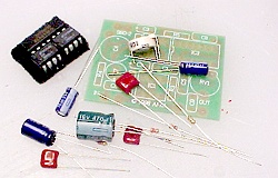 |
Now we turn our attention to
the circuit board. You should have gathered all of the
components together before starting. It is a good idea to
keep the IC's in conductive foam until ready to install. Along with the circuit board itself, there should be 3 IC's, 4 electrolytic capacitors, 3 mylar capacitors, a circuit board mounting potentiometer, and 3 resistors. |
||
 |
The circuit board is
constructed in "layers", with like-sized groups
of components installed, and soldered to the board,
together. The first layer I install are the IC's. Each is placed into the board, noting the position of the notch at the end of the IC, or the depressed dot at pin one. Then the board is turned over, and two diagonal pins on each IC are soldered to hold the IC in place. Check each IC once more for seating and orientation ( make sure ALL of the pins are through the circuit board ! ) then solder all of the remaining pins to the circuit board. It is not necessary to clip the IC pins short after soldering. |
||
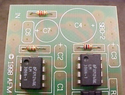 |
The next layer is the resistors.
These may be installed in either direction. The only
thing you need to follow is the color coding...
In the picture, R4 is at the top left. Below R4 is R1, and to the right is R2. All component positions are silkscreened on the circuit board. |
||
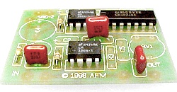 |
The next layer is the mylar film capacitors. These
may also be installed in either direction. Two of the
caps are .022uf, and the other is .047uf. The markings
may vary depending on the manufacturer. The last ones I
got from the parts list were marked 223J and 473J
respectively. The larger cap ( .047uf ) goes into the C1 position - in the middle of the board. The two smaller caps go to the spots for C6 and C9. |
||
|
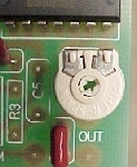
The next component to go on the board is the
adjustable potentiometer, or pot. This is the control
used to set the output level ( volume ) of the Simple
Bat Detector circuit. Insert the leads of the pot into the circuit board from the component side. Then turn the board over and fold down the tabs, as shown in the picture, and solder. Folding the tabs over assures a good mechanical mount and will minimize the possibility of solder joint failure over time. |
||
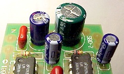 |
The last group of components to go on the board are
the electrolytic capacitors. These are the ones that you
need to pay careful attention to, as they are polarized,
and must only be inserted one way! Note in the picure that there is a white band on the side of the capacitor package. The band indicates the negative lead. The circuit board has a plus sign ( + ) indicating where the positive lead goes. So the lead with the band IS NOT the one that goes to the ( + ) on the circuit board. |
||
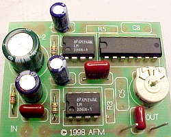 |
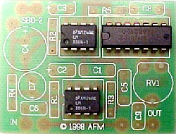
Install the 470uf capacitor at C4, the 220uf
capacitor at C7, and the two 10uf capacitors at C2 and C3.
When you clip the leads off the 470uf capacitor, install
them at the output pads, as shown. Hint: bending a small hook at one end of each of the leads will keep them from falling through when you are soldering them. At this point, the circuit board assembly is complete. Note that there are 4 components that are not installed: R3, R5, C5 and C8. These components are many times used with LM386 IC's, but, for the best ultrasound performance, they are not used in the Simple Bat Detector. |
||
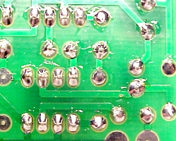 |
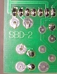
Now it's time to do a careful check of the bottom of
the circuit board. Get a strong light, and a magnifying glass, and examine the solder joints and traces very carefully. The joints should be smooth and shiny. There should not be any solder bridging between two adjacent pads. Also look for solder joints that have too little solder, or leads that may have not been soldered at all. A little extra time taken at this point will make the successful completion of the project more probable !! |
||