| Step 1: Constructing the front panel ... | |
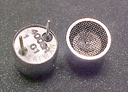 |
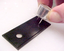
The most important component of
the detector is the transducer. This picture shows the
front and back of a common, metal cased ultrasonic
transducer. To get the best performance from the detector,
it is essential to observe the polarity of the leads on
the transducer. Note that the lead on the lower left of the transducer back is soldered to the case of the transducer - this is the ground lead. The other lead, the hot lead, is electrically isolated from the case by a plastic insulator. |
|
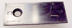
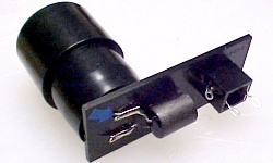
First, we need to drill 3 holes in the front panel of
the PacTec case. The first hole is centered at one end of
the panel and drilled with a 7/32" bit. A transducer mounting hole is then drilled with, a small bit, on the opposite end of the panel. Set it in about 1/4" in from each edge of one corner. After drilling the hole, use the transducer to softly scribe out a short semi-circular line, on a diagonal from the first hole you drilled. Then choose a spot on this line that is as far from the bottom edge of the panel, as the first was from the top, and drill the second transducer mounting hole. With this method, the transducer will end up properly centered on the panel, without doing any really tedious layout work. |
|
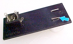
Keeping track of the transducer leads, hot &
ground,
poke the transducer leads through the panel from the
front, and then bend over the hot
lead on the back of the panel to secure the transducer. Note that the larger hole at the left has been chamfered out with a countersink bit. This is done to allow proper seating of the earphone jack, which has a raised shoulder that needs to be accomodated. |
|
You can mark the
transducer case with a red line to indicate which lead is
the hot lead ( see top picture ). Or you can
score a mark on the back of the panel next to the hot lead. Here, I marked the hot lead on the back of the panel with a
blue arrow sticker picture. Whatever method you choose, mark
the hot lead now. Then you can
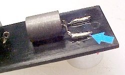
bend down the remaining transducer ground lead and mount the earphone jack to
finish the basic assembly of the front panel. Using a pair of needle nose pliers, twist each of the earphone jack terminals 90 degrees, and position as shown. ( Be sure that the terminal closest to the panel is toward the inside of the panel. ) ( You did mark the hot lead ... yes ??? ) The frequency response of some transducers can be enhanced by adding a small detuning coil across them - the Mouser / Kobitone transducer currently on the parts list is an example. If you are not using a detuning coil, skip the next step. |
|
|
|
The detuning coil is a ferrite encased component that
flattens out the highly peaked tuned frequency of the
transducer. This lets the Simple Bat Detector
respond to a wider portion of the ultrasound spectrum ...
which means a better chance at hearing various species of
bats !! The coil is simply soldered across the transducer leads, on the back side of the front panel. A little A/C glue is used to anchor the mass of the coil permanently in place. |
|
As a final touch, I like to add
a plastic snoot, made from an irrigation adapter
that is press fitted over the transducer. The snoot
provides more directionality to the detector's pickup
pattern, and provides some protection for the transducer.
Now, take a break. You've done the hardest part !!! |