.
The Data Recorder Platform
.
Based on the Arduino Uno...


Many of the projects I have worked with over the years involved some form of data collecting. First it was data regarding streamside fish egg incubators in Idaho... then there were data loggers for weather info ... and radiation levels ... and now bat call data and bat activity levels.

For each one of these applications I had to search out a data logging solution to record the data my equipment was producing. Most of the time I used a commercially available hardware platform to do the work ... but those kept disappearing from the market. Recently, Frank and I have been experimenting with the Arduino system, and it has turned out to be very adaptive to our work.

Then I realized that I could use what I've learned from our Arduino experiments to make an optimized general purpose data logging solution that could be applied to any data collecting project ... and be something that we would have complete control over ... it wouldn't disappear from the market !! This was the birth of the idea that led to the Data Recorder Platform, or DRP.
The DRP is shown to the left. It has an ATMEGA-328 microcomputer as it's heart, seen to the right side of the board. The ATMEGA is programmed with an Arduino UNO bootloader, so can load and run Arduino programs. The ATMEGA is clocked with a 16 MHz crystal oscillator to make timing as accurate as possible.

Just to the left of the processor is a TMP36 analog temperature sensor. There is also a pair of resistors that provide an analog voltage to track the battery level that is powering the DRP.

In the middle of the circuit board is the DS1307 RTC/Calendar chip, with its crystal and backup battery. This allows accurate date and time stamping of the data collected.

On the upper left you can see there is an SD card holder, interfaced with the processor via a 3.3 volt level shifting IC. The on-board 5 volt and 3.3 volt regulators are just to the right of the two position power connection terminal block. There is also a reverse voltage protection diode.

A lot of the processor I/O is dedicated to the SD card, RTC, temperature and battery measurement. There are seven ATMEGA I/O ports that are made available at the DRP headers for use by a stacked shield. Two of these, analog 2, and digital 2, are meant to be the primary data inputs. The other five pins, digital 5, 6, 7, 8, & 9, are available for shield peripheral functions - like actuating relays, lighting LED's, driving piezo sounders, or monitoring push button switches. The headers are organized the same as the Arduino UNO, Rev 3, and also provide Vin, 5V, Reset, and ground connections. There is also a 4 position header port that can be optionally used to connect a serial device. I use this port as a connection to the Arduino IDE, via an FTDI interface, for development and programming. Most of the time, the ATMEGA chip will be preprogrammed when a DRP is built, and the serial port is not needed. Here is a link for the schematic diagram of the DRP.

Below are a couple of examples of the types of data logging devices that can be achieved with the DRP. The board to the left is a background radiation monitor and logger. The board to the right is a bat call data logger. You can see how these data logging devices are quite compact, and have functional layouts. You might also notice that the circuits are built with primarily through-hole components, and a minimum of surface mount connections. So the boards are relatively easy to construct and maintain.

If these data logging devices had been built with standard Arduino UNO's and data logging shields, the stack would need at least three levels. There would be more potential bad connections with two layers of header connections. And the UNO, and most commercially available shields, would have peripheral circuits ( like LED's ) that would not be necessary, and would actually waste power.

Power usage is one element that led to developing the DRP. With the UNO's un-needed auxiliary circuits left out, the DRP draws only 16ma when fully active, and can drop it's power requirements to less than 1ma when sleeping. This is a key issue when deploying battery operated devices.

The voltage regulator on the DRP is a low power LDO device that isn't designed to supply power to a stack of 3 or 4 boards, so power savings is added. If an attached shield requires any significant power, it should provide it's own regulators and derive power from the Vin supply.

Use these links to learn more about the Radiation Sensor and Bat Call Sensor shields that have been used in these examples. I have a couple of other projects in mind that will employ the DRP, so the design is already proving adaptable and worth the design effort. I am basically planning on using the DRP in quantity to supply bat call data recorders to bat researchers, and haven't considered providing these boards beyond that scope... but I'm always happy to hear of other applications and ideas that the DRP may support. So, feel free to email me if you have any further questions, or comments, about the Data Recorder Platform.


UPDATE: June, 2016 ...

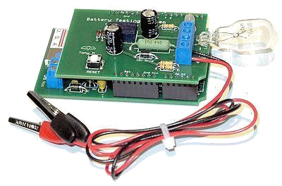
It seems I keep finding new uses for the Data Recorder Platform. To the left is a shield that I designed to allow me to test the many 12 volt gel cell batteries I have. The Battery Testing System shield basically connects a load ( the light bulb ) to the battery and measures, and logs, the voltage and current drain each minute.

When the battery has depleted to a preset voltage, the relay disconnects the battery to stop the test, and further discharge. I then pull the data into Excel and plot the discharge curve ... and I can calculate the true Amp-hour capacity of the battery. It works pretty slick.

I've also designed two stacking shields for the data recorder that will be used in high altitude balloons ... but that is another story. I'm sure I'll find still more applications as time moves on.


Tony Messina - Las Vegas, Nevada - email:
T-Rex@ix.netcom.com - First published January, 2015