| Now we need to begin
working with the Arduino UNO board. I won't go
into how to write programs, or how to use the Arduino
software to load sketches. There are better web resources
for those types of information. I will continue on
expecting that you have mastered the basics of working
with the Arduino environment. As a reminder, the
official Arduino website is at: www.arduino.cc In order to configure the ArduBat, you
need to have an idea of what input/output pins are used
for the various parts of your project. Below is the
Pinout Map that I developed for my ArduBat
project. I am using an Adafruit # 1141 data logging shield, as well as the ArduBat
shield. I am also using several analog sensors, and a
bistable latching relay, but these aren't as important
for the initial configuration of the ArduBat. In
the list you can see there are 6 analog data pins, and 14
digital data pins. On the pinout map I have used colors
to group the way the pins are being used.
|
 |
All of the pins in red are needed by the Arduino board and
operating system, so these shouldn't be used ( unless you
know what you are doing :-) . The
pins in green are defined and used on the Adafruit
data logger card, and should also be reserved. Even if
you use a different shield down the road, the D10 through
D13 pins will still be used by the SD card library to
access the SD card.
|
 The orange
pins are the ones that are
important to configuring the ArduBat. These are
the pin allocations that the ArduBat uses for the LED,
Push-button, and bat call connections. These are also the
pins that are defined in the various sketches ( programs
) that are on this web site. Most of these connections
were configured using wire jumpers on earlier ArduBat
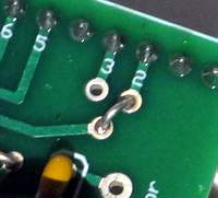
boards. But only the Div 32 Bat Call Data
is jumper configured now. Normally, it is set to D2 as
shown to the right. If, for some reason you can not use D2
for the ArduBat output, D3 is available as a jumper
option. D2 and D3 are the two standard interrupt pins on
the Arduino UNO. The orange
pins are the ones that are
important to configuring the ArduBat. These are
the pin allocations that the ArduBat uses for the LED,
Push-button, and bat call connections. These are also the
pins that are defined in the various sketches ( programs
) that are on this web site. Most of these connections
were configured using wire jumpers on earlier ArduBat
boards. But only the Div 32 Bat Call Data
is jumper configured now. Normally, it is set to D2 as
shown to the right. If, for some reason you can not use D2
for the ArduBat output, D3 is available as a jumper
option. D2 and D3 are the two standard interrupt pins on
the Arduino UNO. |
| The pins annotated in black
are the analog data pins that I have used in the past for
more data collection options. |
 |
The next step is to stack the ArduBat
onto the Arduino UNO ( rev 3 ) board, and
connect it to the computer that is running the Arduino
software. But before you do this,
I recommend a couple of modifications to the UNO R3
board...
Because of the close spacing, I
recommend clipping off the pins of the two connectors
circled in green in the image to the left.
I also used a couple of layers of kapton
tape to insulate the USB connector ( circled in red ) on
the UNO from the bottom of any boards placed on
top. Electrical, or heavy cellophane tape are also useful
options here.
If you don't make these modifications,
you will need to be very careful that you don't short any
connections on the bottom of added shields when they are
placed on top of the UNO !!
|
 |
After stacking the ArduBat on the UNO,
and connecting it via the USB to your programming
computer, you need to supply 12 volts to the Arduino
external power connector. This provides the power for the
bat detector circuit on the ArduBat shield. It's
not really necessary to have the earphone connected quite
yet ... Download, compile, and
load the Demo / Test Sketch ( ABDemo.ino
).
When you press and hold the F1 push-button,
the Green LED should light. When you press and hold the F2
push-button, the Red LED should light. When you jingle
keys closely in front of the transducer, the Yellow LED
should flash. And, when you press the RST push-button,
the Red and Green LED's will reset to off.
If all of these tests worked,
congratulations. Your ArduBat is almost ready to
go.
|
At this point in the
construction of the ArduBat, it is still a bit
deaf. Only the first stage sensitivity / gain has been
set. In the next steps we need to set the gain of the
second stage. This procedure will determine the final
sensitivity of the entire bat detector circuit.
To be able to hear what we are doing, we need to
temporarily be able to connect an earphone to the Monitor
output, near the transducer, of the ArduBat. |
|
I use a 3 pin header strip section as
a plug. Clip out the middle pin and wire the earphone to
the shorter end of the remaining two pins. Then squeeze
the two longer pins together just a little. If you get the spacing correct, you can simply
connect the earphone by lightly pressing the header
"plug" into the monitor pads on the ArduBat
PCB.
Of course you can also solder the wires
of the earphone to the Monitor pads if you want
the earphone to be connected permanently ... but I find
that the earphone is usually not necessary for most
projects.
|
| It is important to
consider the environment that the Simple Bat Detector
circuit is in with the ArduBat configuration.
Electrical noise will be transmitted to it from the
digital circuits below it, as well as via the power
connections ( including the AC wall-wart supply, if used
) . So to set up the best test conditions I recommend
using the ArduBat, stacked with the Arduino
... running the demo sketch, as above. The ArduBat
should be connected to the computer with the USB
connector, and should have a 12 volt wall-wart power
supply plugged in to the Arduino power connector.
( Without 12 volts to the Arduino, the bat
detector circuits are not powered !! ) This situation
maximizes the static background noise from the computer
and power sources, yet simulates the actual digital noise
during a bat pulse sampling period ... when we really
need the bat detector circuit to be clean and clear of
interference. And note ... contrary to the picture above,
stretch out the earphone cord and keep it away from the
transducer to avoid feedback oscillation while you are
testing !! |
|
With the above conditions met, run the
demo program and press either the F1 or F2 buttons to
illuminate an LED. Softly bend
the leads of a 150 ohm resistor, and gently plug it in to
the pads for the second stage gain resistor on the ArduBat
board ( marked with a *** ) ... see the circled area of
the picture to the left.
Now, brush your fingers together and
see that the sound is picked up at least a foot away from
the transducer ... this indicates good sensitivity. Is
the circuit quiet when you are not rubbing your fingers
?? Good, then you are set.
If there is noise or oscillation when
you are not rubbing your fingers, you may have to reduce
the gain ... repeat the process with the next larger
resistor ... 220 ohms and then 470 ohms etc. When you
find the smallest value resistor that gives you the best
sensitivity, with no noise, then you can solder it on to
the circuit board, and the ArduBat configuration
is complete.
|
| I find that 150 ohms works
very well for the transducer and detuning coil listed in
the parts list. In actual
use, many of the ArduBat projects you build will
likely run disconnected from the computer, or on a
battery instead of a wall-wart. So the real world
applications should be quieter, as far as electrical
noise is concerned. Still, when you do run more complex
programs, you will undoubtedly hear all sorts of noise
from the bat detector circuit when program loops are
toggling I/O pins, activating relays, writing or reading
files from SD cards, etc. This is fine ... as long as the
noise goes away when the Bat Pulse sampling
routines are running. This adds a bit of a challenge to
your programming ... writing code that is quiet :-) At this point there are
several options... learning more about the Demo
Sketch, looking at a logging
application, or maybe troubleshooting
a problem with your ArduBat
... in any case, you now have a fully functional ArduBat
shield, and you are ready to experiment. Good luck with
your project !
|