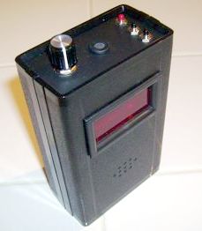
The Digital "Bat Scanner"
Detector
.
 |
This project has come
to an end. Several key components were either
discontinued, or about to be discontinued. So, after a
run of about 6 years, we decided to close this project,
and concentrate our efforts on some of the newer projects
we have going. Check out the ArduBat project, and the Simple Bat
Detector.
In order to provide
continuing support for those who have built the Bat
Scanner, we are keeping this archived information
available here.
I am still happy to
answer questions and offer assistance to anyone who has
built this kit. I can even supply some replacement parts
... but not circuit boards. Just email
me.
|
The key idea behind the scanning heterodyne bat
detector was to use a 16F628A PIC microprocessor to generate the
mixing frequency for an otherwise standard heterodyne detecting
circuit. The program that was developed allowed the PIC to enable
the heterodyne detector to scan frequencies between any two
predefined decades, from 10kHz to 80kHz, in 2 kHz steps. It was
also possible to turn off the scanning and manually set the
frequency if desired. The PIC also provides the detector with a
digital LED display of the frequency that the detector is tuned
to.
But there was still one more feature to be
added ... a special detection circuit to let the PIC determine
when there was a sound. This made it possible to automatically
stop or pause the scanning when a sound was detected ... pretty
cool :-)
Here is a simplified block diagram of the
scanning heterodyne detector:

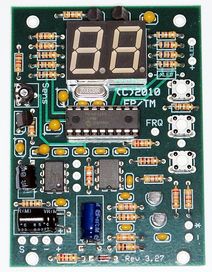
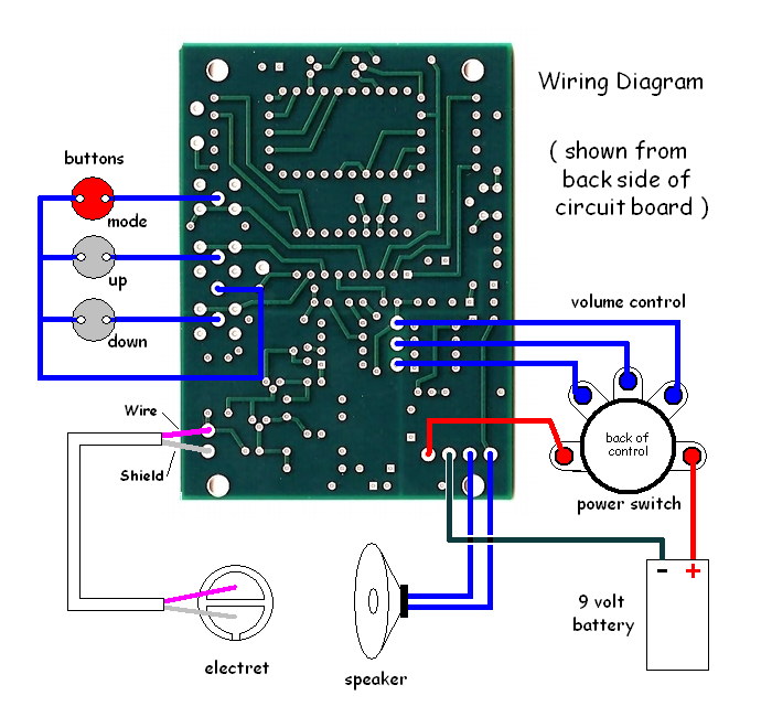
An electret microphone signal is
fed to a two transistor preamplifier which selectively amplifies
the frequencies in the ultrasound range. The preamplified
ultrasound is fed to an NE612 mixer IC that converts the
ultrasound to audible sound, using the reference frequency from
the PIC processor. The audible sound is fed to an LM-386
amplifier IC and speaker, as well as back to the PIC so that it
can detect when sound is present to pause or stop scanning. Three
buttons on the PIC processor allow selection of the tuned
frequency, as well as enabling the scanning mode and allowing the
setting of various operating parameters.
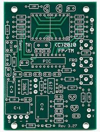 |
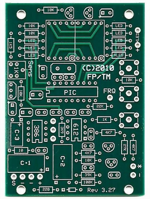
Frank worked on the code for the PIC
and made up the first prototypes ... and with a little
tweaking they worked well. My
job was to design the circuit board, and put some final
tweaks to the circuitry. We ended up with a 4 layer
circuit board. The board has heavy traces, a split power
plane, ground plane, solder masking on both sides, and a
very readable silk-screened parts layout.
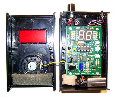
We, and others, have successfully
constructed many Bat Scanner detectors over the
length of the project.
|
 |
The idea of a scanning heterodyne wasn't really
new. There have been a couple of expensive commercial detectors
that have had scanning features. But this detector was relatively
low in cost, less than $100 to build, and has a very efficient
design.
Notes
on Maintenance ...
Circuit board repairs require a decent
temperature controlled soldering iron with a small chisel
or conical tip. Good lighting, and a magnifying glass are
essential for working with some of the small parts. You
also need to be mindful of ESD precautions when handling
the semi-conductors - especially the PIC microprocessor
chip.
All of the original construction
manuals for the Bat Scanner are still online.
The firmware HEX
file for the PIC processor is also here. If you need a
new 16F628A PIC for your Bat Scanner, and don't
have a PIC programmer, email me about getting
a replacement.
|
 |
Tony Messina - Las Vegas, Nevada
- email: T-Rex@ix.netcom.com
